Control Valve Symbol
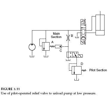
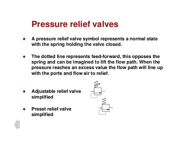
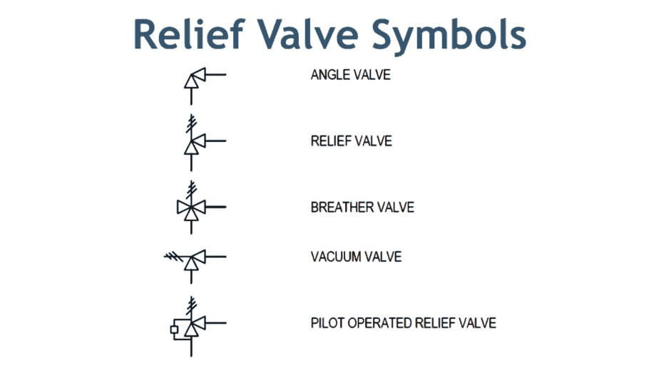
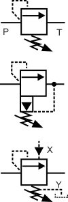
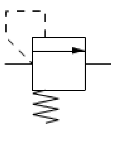
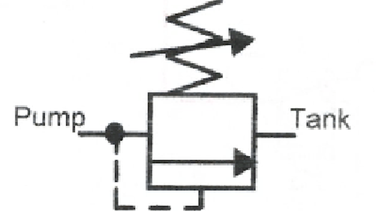
Control is shown by normal actuation symbols in Figure 48b, for example, the spring pushes the valve right, decreasing flow, and pilot pressure pushes the valve left, increasing flow This represents a pressurerelief valve which would be connected into a hydraulic system as shown in Figure 48c.

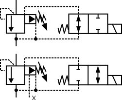
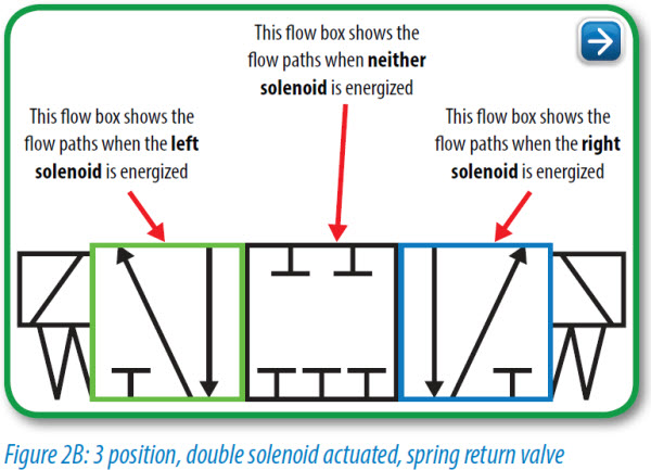
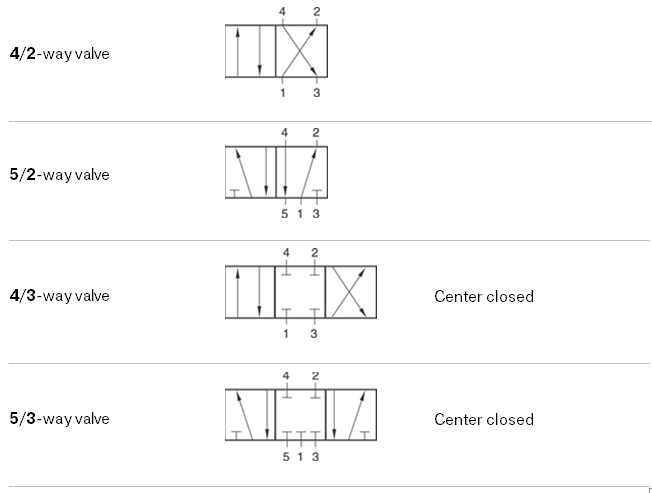
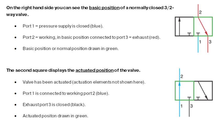
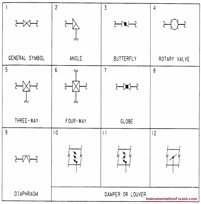
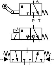
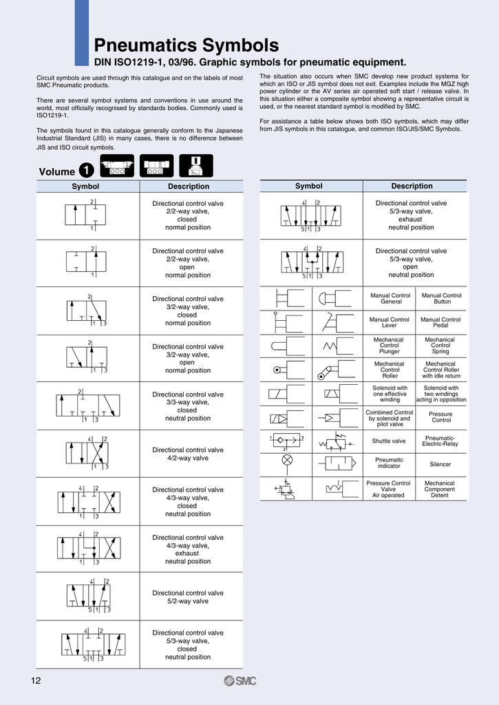
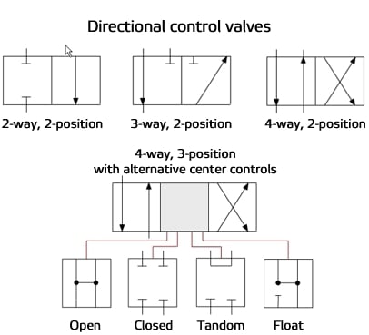
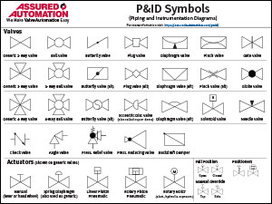
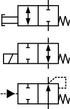
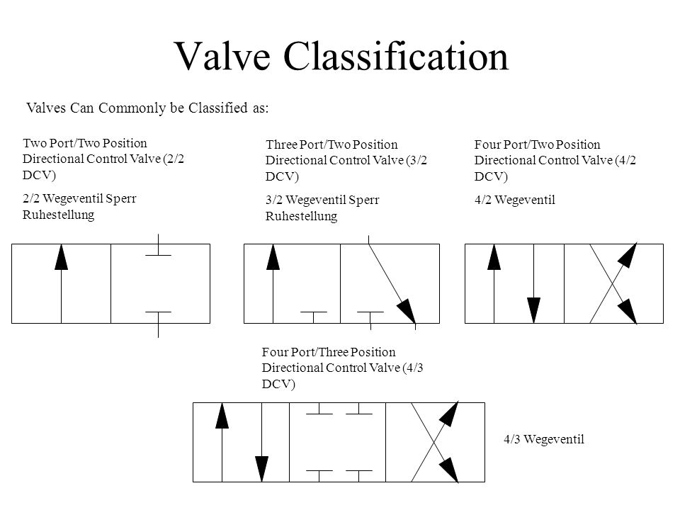
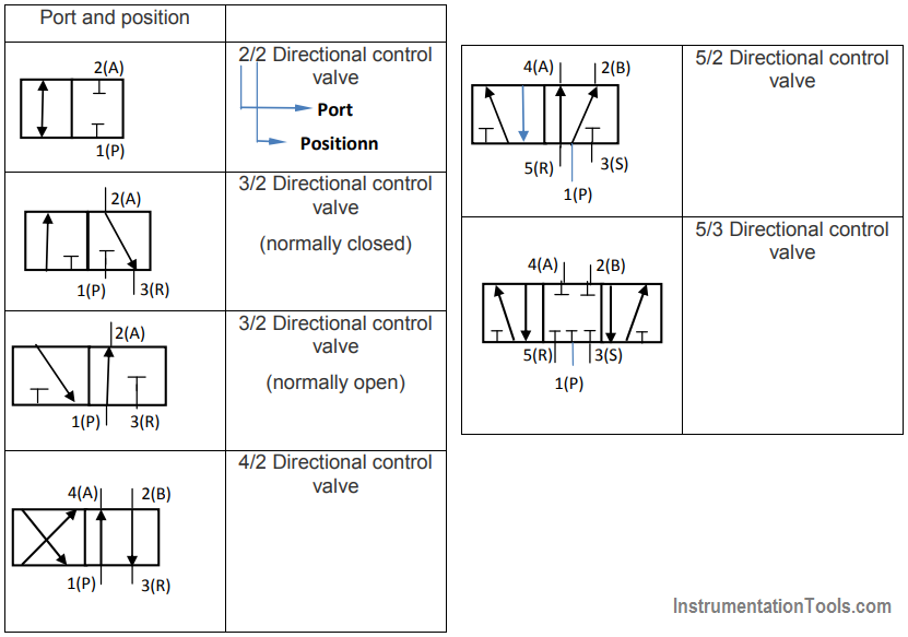
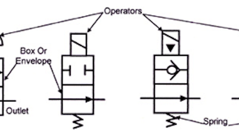
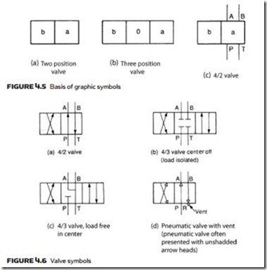
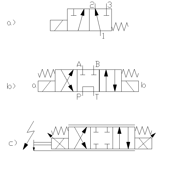
Control valve symbol. The symbol for directional control valve is made of number of square boxes adjacent to each other depending on the number of positions Connections to the valve are shown on these squares by capital lettersusually they are named only in their normal position and not repeated in other positionsactuation system of the valve is also designated. In case none of the valves are actuated, the piston rod stays in last position (The symbol at the bottom displays an FRLunit (filter, regulator, lubricator) The functions of cylinders as well as of airpreparation units will be discussed in a later chapter) 3/2way valves 3/2way valves are mostly used to control single acting actuators. ISA SYMBOLOGY The symbology for the identification of the measurement and control instrumentation on the flow and process diagrams and on the P&ID (Piping & Instrument Diagram), commonly called P&I (Piping & Instrumentation), is generally compliant with the Standard ISA (Instrumentation Society of Automation) identified as S5, that is composed of identification codes and graphic symbols.
The symbol for directional control valve is made of number of square boxes adjacent to each other depending on the number of positions Connections to the valve are shown on these squares by capital lettersusually they are named only in their normal position and not repeated in other positionsactuation system of the valve is also designated. ISA SYMBOLOGY The symbology for the identification of the measurement and control instrumentation on the flow and process diagrams and on the P&ID (Piping & Instrument Diagram), commonly called P&I (Piping & Instrumentation), is generally compliant with the Standard ISA (Instrumentation Society of Automation) identified as S5, that is composed of identification codes and graphic symbols. Schematic symbols are used to identify and graphically depict the function of fluid power components Recognizing and understanding schematic Valves control the direction and amount of flow while actuators are the work producers such as cylinders and rotary actuators.
Directional Control Valves Directional control valve (2 ports / 2 positions)Normally closed directional control valve with 2 ports and 2 finite positions Hydraulic Schematic Symbols ShutOff ValveSimplified symbol Accumulators Filters, Water Traps, Lubricators and Miscellaneous Apparatus Filter or Strainer Water Trapwith manual. The symbol for directional control valve is made of number of square boxes adjacent to each other depending on the number of positions Connections to the valve are shown on these squares by capital lettersusually they are named only in their normal position and not repeated in other positionsactuation system of the valve is also designated. Control is shown by normal actuation symbols in Figure 48b, for example, the spring pushes the valve right, decreasing flow, and pilot pressure pushes the valve left, increasing flow This represents a pressurerelief valve which would be connected into a hydraulic system as shown in Figure 48c.
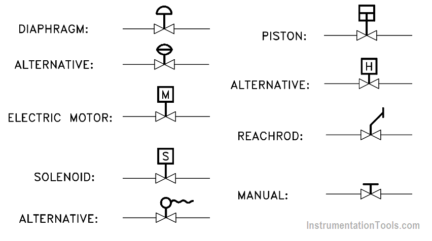
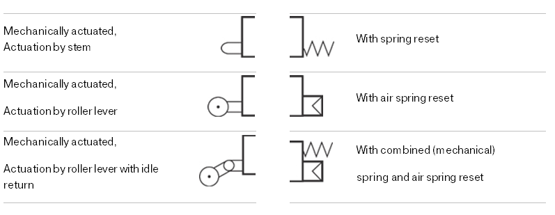
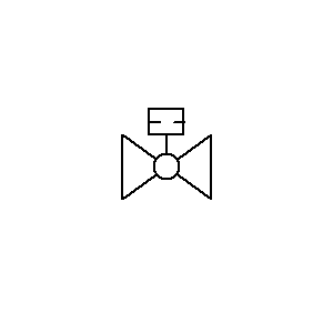
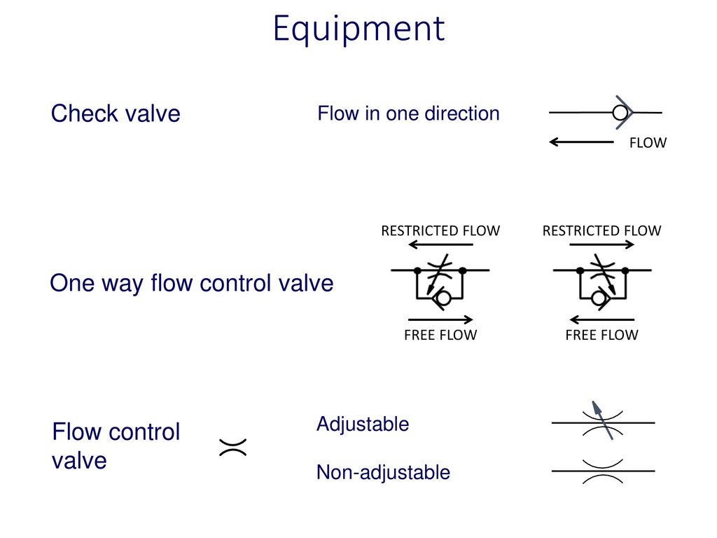
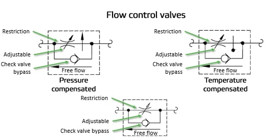
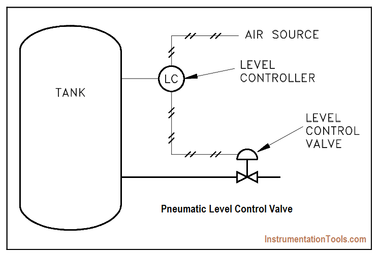
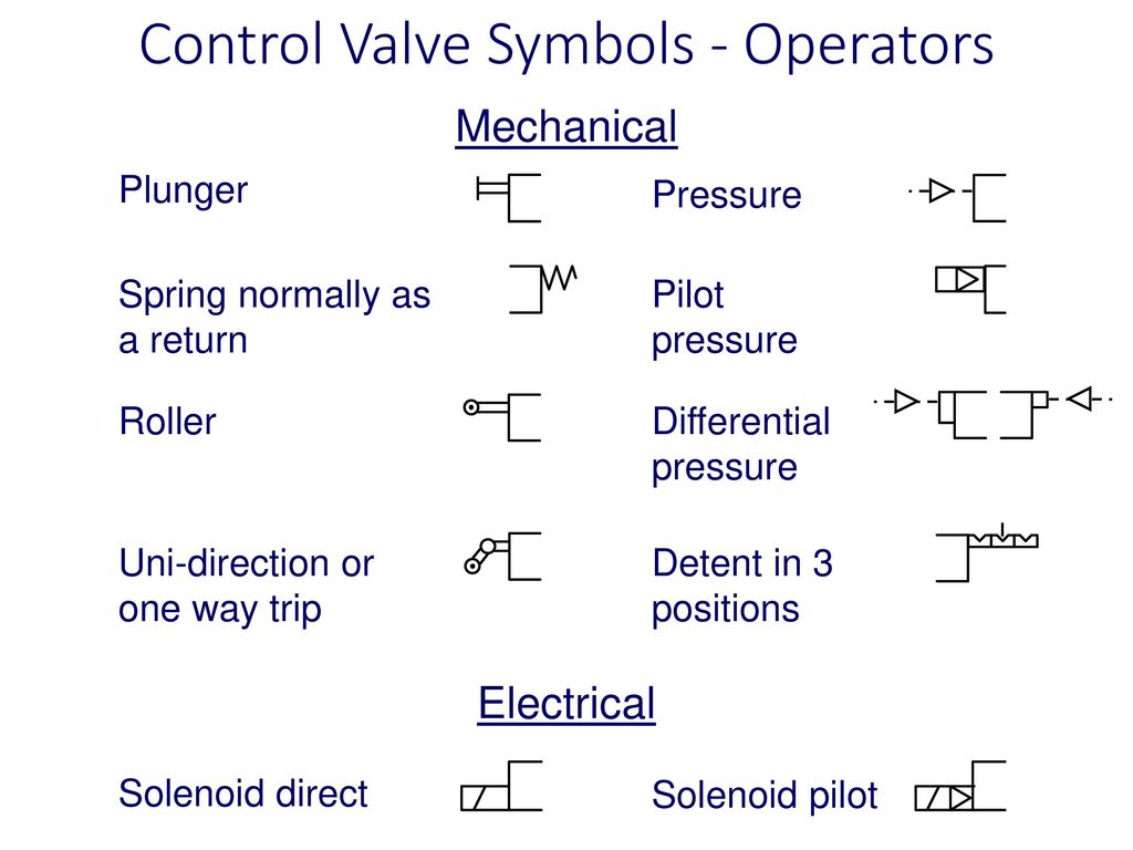
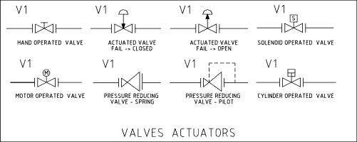
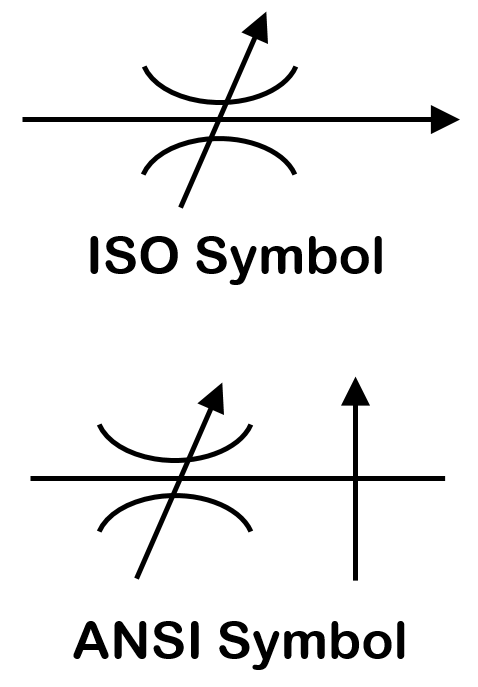
Symbol Via electric stepper motor Via solenoid, e g with two counteracting solenoids Nonreturn valve without spring Quick exhaust valve Shuttle valve Oneway flow control valve, adjustable Nonreturn valve with spring Dualpressure valve Via solenoid or manual override and pilot valve Flow control valve Nonreturn valve Connection. 2 interlock number and proper symbol (dcs or plc) will be shown on process p&id 3 for valves located in pits with extended valve stems / actuators, limit switch and positioner will be located outside the pits 4 safety solenoid valve (sy) is to trip the valve to its failure position 5. Control valves are symbolized by combining the appropriate valve symbol and actuator symbol, as illustrated in Figure 2 Control valves can be configured in many different ways The most commonly found configurations are to manually control the actuator from a remote operating station, to automatically control the actuator from an instrument.
Schematic symbols are used to identify and graphically depict the function of fluid power components Recognizing and understanding schematic Valves control the direction and amount of flow while actuators are the work producers such as cylinders and rotary actuators. ISA SYMBOLOGY The symbology for the identification of the measurement and control instrumentation on the flow and process diagrams and on the P&ID (Piping & Instrument Diagram), commonly called P&I (Piping & Instrumentation), is generally compliant with the Standard ISA (Instrumentation Society of Automation) identified as S5, that is composed of identification codes and graphic symbols. Symbol Via electric stepper motor Via solenoid, e g with two counteracting solenoids Nonreturn valve without spring Quick exhaust valve Shuttle valve Oneway flow control valve, adjustable Nonreturn valve with spring Dualpressure valve Via solenoid or manual override and pilot valve Flow control valve Nonreturn valve Connection.
Directional Control Valves Directional control valve (2 ports / 2 positions)Normally closed directional control valve with 2 ports and 2 finite positions Hydraulic Schematic Symbols ShutOff ValveSimplified symbol Accumulators Filters, Water Traps, Lubricators and Miscellaneous Apparatus Filter or Strainer Water Trapwith manual. 2 interlock number and proper symbol (dcs or plc) will be shown on process p&id 3 for valves located in pits with extended valve stems / actuators, limit switch and positioner will be located outside the pits 4 safety solenoid valve (sy) is to trip the valve to its failure position 5. In case none of the valves are actuated, the piston rod stays in last position (The symbol at the bottom displays an FRLunit (filter, regulator, lubricator) The functions of cylinders as well as of airpreparation units will be discussed in a later chapter) 3/2way valves 3/2way valves are mostly used to control single acting actuators.
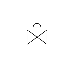
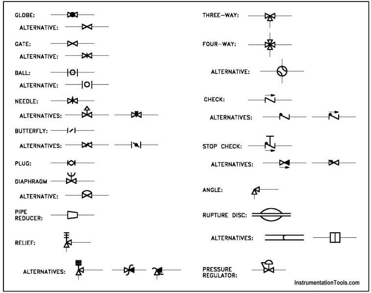
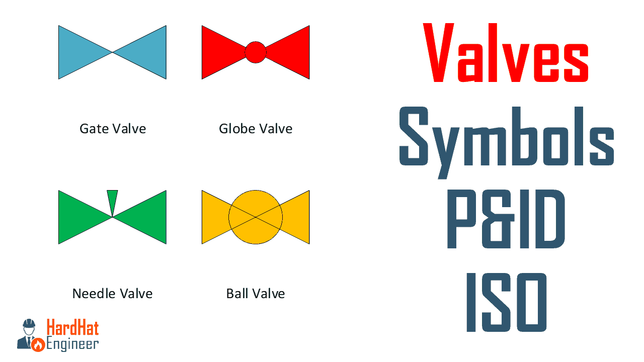
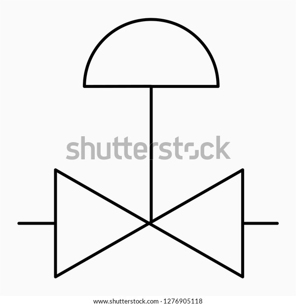
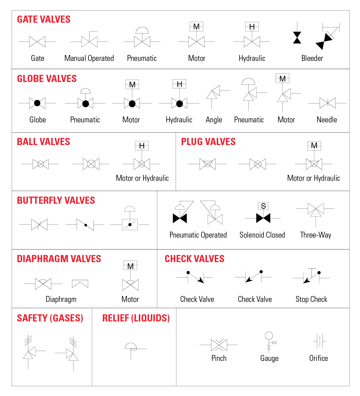
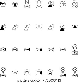
Control is shown by normal actuation symbols in Figure 48b, for example, the spring pushes the valve right, decreasing flow, and pilot pressure pushes the valve left, increasing flow This represents a pressurerelief valve which would be connected into a hydraulic system as shown in Figure 48c. Legend & Symbol Valves Gate Valve Ball Valve Globe Valve Check Valve Butterfly Valve Hand Control Valve Motor Operated Valve Control Valve c/w Positioner. In case none of the valves are actuated, the piston rod stays in last position (The symbol at the bottom displays an FRLunit (filter, regulator, lubricator) The functions of cylinders as well as of airpreparation units will be discussed in a later chapter) 3/2way valves 3/2way valves are mostly used to control single acting actuators.
Control valve symbol is incorrect and the substitution palette shows instrument symbols Note This may occur after making a substitution of the valve body symbol. Control valve symbol is incorrect and the substitution palette shows instrument symbols Note This may occur after making a substitution of the valve body symbol. Schematic symbols are used to identify and graphically depict the function of fluid power components Recognizing and understanding schematic Valves control the direction and amount of flow while actuators are the work producers such as cylinders and rotary actuators.
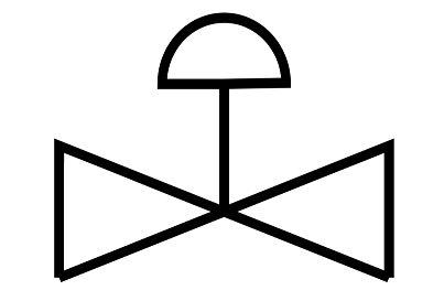
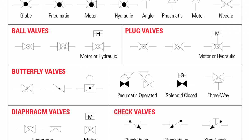
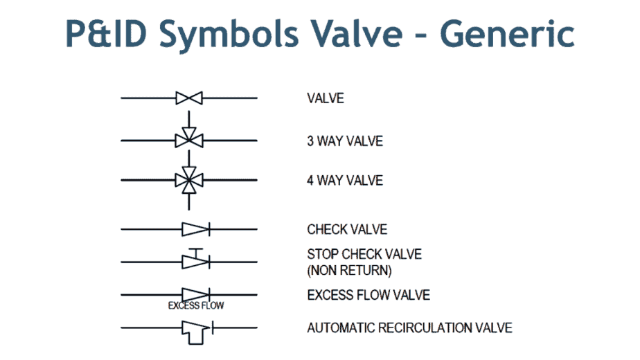
Legend & Symbol Valves Gate Valve Ball Valve Globe Valve Check Valve Butterfly Valve Hand Control Valve Motor Operated Valve Control Valve c/w Positioner. Symbol Via electric stepper motor Via solenoid, e g with two counteracting solenoids Nonreturn valve without spring Quick exhaust valve Shuttle valve Oneway flow control valve, adjustable Nonreturn valve with spring Dualpressure valve Via solenoid or manual override and pilot valve Flow control valve Nonreturn valve Connection. Control Valve PistonOperated Valve Check Valve Back Pressure Regulator Plug or Cock Valve Closed Gate Valve Check Valve 2 Butterfly Valve Angle Valve HandOperated Piping and Instrument Diagram Standard Symbols Detailed Documentation provides a standard set of shapes & symbols for documenting P&ID and PFD, including standard shapes of.
In case none of the valves are actuated, the piston rod stays in last position (The symbol at the bottom displays an FRLunit (filter, regulator, lubricator) The functions of cylinders as well as of airpreparation units will be discussed in a later chapter) 3/2way valves 3/2way valves are mostly used to control single acting actuators. Directional Control Valves Directional control valve (2 ports / 2 positions)Normally closed directional control valve with 2 ports and 2 finite positions Hydraulic Schematic Symbols ShutOff ValveSimplified symbol Accumulators Filters, Water Traps, Lubricators and Miscellaneous Apparatus Filter or Strainer Water Trapwith manual. Control valves are symbolized by combining the appropriate valve symbol and actuator symbol, as illustrated in Figure 2 Control valves can be configured in many different ways The most commonly found configurations are to manually control the actuator from a remote operating station, to automatically control the actuator from an instrument.
2 interlock number and proper symbol (dcs or plc) will be shown on process p&id 3 for valves located in pits with extended valve stems / actuators, limit switch and positioner will be located outside the pits 4 safety solenoid valve (sy) is to trip the valve to its failure position 5. The symbol for directional control valve is made of number of square boxes adjacent to each other depending on the number of positions Connections to the valve are shown on these squares by capital lettersusually they are named only in their normal position and not repeated in other positionsactuation system of the valve is also designated. 2 interlock number and proper symbol (dcs or plc) will be shown on process p&id 3 for valves located in pits with extended valve stems / actuators, limit switch and positioner will be located outside the pits 4 safety solenoid valve (sy) is to trip the valve to its failure position 5.
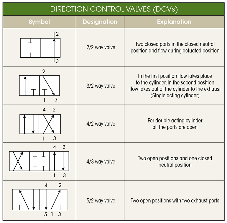
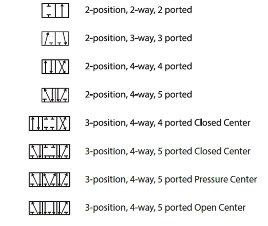
The SP53 committee in developing ISAS53, "Graphic Symbols for Distributed Control/Shared Display Instrumentation, Logic and Computer Systems" The key elements of ISAS53 have. Valve Symbols Valves can have two or more ports and control the flow of the media between those ports The circuit function of the valve describes the different switching states it has For a systematic representation, symbols are used This article explains the logic behind valve symbols Name circuit functions;. Valve Symbols Valves can have two or more ports and control the flow of the media between those ports The circuit function of the valve describes the different switching states it has For a systematic representation, symbols are used This article explains the logic behind valve symbols Name circuit functions;.
Control valves are symbolized by combining the appropriate valve symbol and actuator symbol, as illustrated in Figure 2 Control valves can be configured in many different ways The most commonly found configurations are to manually control the actuator from a remote operating station, to automatically control the actuator from an instrument. Control Valve PistonOperated Valve Check Valve Back Pressure Regulator Plug or Cock Valve Closed Gate Valve Check Valve 2 Butterfly Valve Angle Valve HandOperated Piping and Instrument Diagram Standard Symbols Detailed Documentation provides a standard set of shapes & symbols for documenting P&ID and PFD, including standard shapes of. Control valves are symbolized by combining the appropriate valve symbol and actuator symbol, as illustrated in Figure 2 Control valves can be configured in many different ways The most commonly found configurations are to manually control the actuator from a remote operating station, to automatically control the actuator from an instrument.
Control Valve PistonOperated Valve Check Valve Back Pressure Regulator Plug or Cock Valve Closed Gate Valve Check Valve 2 Butterfly Valve Angle Valve HandOperated Piping and Instrument Diagram Standard Symbols Detailed Documentation provides a standard set of shapes & symbols for documenting P&ID and PFD, including standard shapes of. The SP53 committee in developing ISAS53, "Graphic Symbols for Distributed Control/Shared Display Instrumentation, Logic and Computer Systems" The key elements of ISAS53 have. Control valve symbol is incorrect and the substitution palette shows instrument symbols Note This may occur after making a substitution of the valve body symbol.
The SP53 committee in developing ISAS53, "Graphic Symbols for Distributed Control/Shared Display Instrumentation, Logic and Computer Systems" The key elements of ISAS53 have. ISA SYMBOLOGY The symbology for the identification of the measurement and control instrumentation on the flow and process diagrams and on the P&ID (Piping & Instrument Diagram), commonly called P&I (Piping & Instrumentation), is generally compliant with the Standard ISA (Instrumentation Society of Automation) identified as S5, that is composed of identification codes and graphic symbols. Control valve symbol is incorrect and the substitution palette shows instrument symbols Note This may occur after making a substitution of the valve body symbol.
Valve Symbols Valves can have two or more ports and control the flow of the media between those ports The circuit function of the valve describes the different switching states it has For a systematic representation, symbols are used This article explains the logic behind valve symbols Name circuit functions;. Schematic symbols are used to identify and graphically depict the function of fluid power components Recognizing and understanding schematic Valves control the direction and amount of flow while actuators are the work producers such as cylinders and rotary actuators. Control is shown by normal actuation symbols in Figure 48b, for example, the spring pushes the valve right, decreasing flow, and pilot pressure pushes the valve left, increasing flow This represents a pressurerelief valve which would be connected into a hydraulic system as shown in Figure 48c.
The SP53 committee in developing ISAS53, "Graphic Symbols for Distributed Control/Shared Display Instrumentation, Logic and Computer Systems" The key elements of ISAS53 have. Symbol Via electric stepper motor Via solenoid, e g with two counteracting solenoids Nonreturn valve without spring Quick exhaust valve Shuttle valve Oneway flow control valve, adjustable Nonreturn valve with spring Dualpressure valve Via solenoid or manual override and pilot valve Flow control valve Nonreturn valve Connection. Legend & Symbol Valves Gate Valve Ball Valve Globe Valve Check Valve Butterfly Valve Hand Control Valve Motor Operated Valve Control Valve c/w Positioner.
Valve Symbols Valves can have two or more ports and control the flow of the media between those ports The circuit function of the valve describes the different switching states it has For a systematic representation, symbols are used This article explains the logic behind valve symbols Name circuit functions;.

File Symbol Pressure Control Valve Adjustable Svg Wikipedia

P Ids Piping Instrumentation Diagrams And P Id Valve Symbol Library Assured Automation

Control Valves Typical P Id Arrangement Enggcyclopedia
Control Valve Symbol のギャラリー
Valves Symbols
Pressure Relief Valve Symbols
Piping And Instrumentation Symbols Instrumentation Tools

Pressure Control Valve Symbol Icons Download Free Vector Icons Noun Project
Control Valve Symbol Icon Royalty Free Vector Image

Control Valve Symbols Chemical Engineering Blog Facebook
Pneumatic Circuit Symbols Explained Library Automationdirect
Iso Schemes Of Directional Control Valves
Iso Schemes Of Directional Control Valves
Valves Symbols
Control Valve Stroke Test Procedure Instrumentationtools
Piping And Instrumentation Symbols Instrumentation Tools

Common Symbols Used In Pneumatic Systems And Instrumentations Learning Instrumentation And Control Engineering
Iso Schemes Of Directional Control Valves

Pin On Pneumatic
Reading Fluids Circuit Diagrams Hydraulic Pneumatic Symbols

Flow Control Valves Hydraulic Symbology 4
Pilot Operated Relief Valves Hydraulic Circuits Hydraulic Valve

Solenoid Valves Discrete Control System Elements Automation Textbook
For System Diagrams And Component Identification Ppt Download
Control Valve Symbols Control Valves Instrumentation Forum
Q Tbn And9gcrnne1 Iseawvdnarue9f0mgteoqebjmtbud1cyqgmkc4tniyge Usqp Cau
Valve Symbols In P Id Ball Valve Relief Valve And More

Directional Control Valves Symbols Hydraulic Valve
Directional Valve Symbols

Solenoid Valve Symbols

A Guide To Common Hydraulic Symbols Engineeringclicks
Reading Fluids Circuit Diagrams Hydraulic Pneumatic Symbols

Valve Symbols Flow Control Norway As
Q Tbn And9gcq0mfzsen8erkzkmsrwfzek8i2l91jdfsxsdcekaheymmevuvgl Usqp Cau
The Most Common Control Valve Symbols On A P Id Kimray

Valve Symbols Tameson Co Uk
Pnuematic Valve Symbols
P Id Symbols For Valves The Piping Engineering World

Solenoid Valve Symbols
Pneumatics Symbols
Reading Fluids Circuit Diagrams Hydraulic Pneumatic Symbols
Q Tbn And9gcrjku3zsalrvg Uv0pt3nwcnyl Tbd8g4jwpgnpzsy X4ui6cnb Usqp Cau
Valve Symbols In P Id Ball Valve Relief Valve And More
Hydraulic Symbols Zeus Hydratech
P Ids Piping Instrumentation Diagrams And P Id Valve Symbol Library Assured Automation

What S The Difference Between Hydraulic Circuit Symbols Machine Design
Directional Valve Symbols
Q Tbn And9gcrw5ywprdnuzleh02elmmeqo3j Vedtbvnxc8hhh4hybgb Mabg Usqp Cau
Fluid Power Symbols Ppt Video Online Download
Sites Ntc Doe Gov Partners Tr Training textbooks 08 Engineering symbology prints and drawings 2 Mod 2 Engineering fluid diagrams and prints Pdf

Flow Control Valves One Way Flow Control Valve Adjustable Valves Fluid Power Pneumatics Symbols Services Festo Didactic
Valves Symbols
Piping And Instrumentation Symbols Instrumentation Tools

Iso 8 X2132 Self Operating Back Pressure Control Valve
Iso Designation Of Direction Control Valves Control Valves Instrumentation Forum

Gate Valve Symbol Page 1 Line 17qq Com

P Id Symbols For Control Valve Assmbly And Actuators Enggcyclopedia
Pressure Relief Valve Symbols

Simple Set Of Shut Off And Control Valves Vector Symbols And Royalty Free Cliparts Vectors And Stock Illustration Image
What S The Difference Between Hydraulic Circuit Symbols Machine Design
Book 2 Chapter 8 Directional Control Valves Hydraulics Pneumatics

Hydraulic Flow Control Valves Hydraulic Valve

Flow Control Valves Hydraulic Flow Control Valves Hydraulic Schematic Troubleshooting
Control Valve Symbol

Tip 14 Go With The Flow Control Hydraulics Pneumatics

What S The Difference Between Hydraulic Circuit Symbols Machine Design

Hydraulic Reducing Valve Symbols
Control Valve Symbol Shut Off Faucet Stock Vector Royalty Free
Control Valve Symbol High Res Stock Images Shutterstock
Valve Symbols In P Id Ball Valve Relief Valve And More

Directional Control Valves Directional Control Valves Classification By Port Position Count Hydraulic Schematic Troubleshooting

Control Valves Components Selection Types Symbols Installation What Is Piping All About Piping Engineering
Control Valves Graphic Symbols Hydraulics And Pneumatics

Control Valves In P Id Control Valves Instrumentation Forum

Symbols For Hydraulic Pressure Control Valves
Pressure Control Valve Symbol Icon Royalty Free Vector Image
Diaphragm Control Valve Symbol Icon Royalty Free Vector

Hydraulic Symbology 3 Pressure Valves
Tip 18 Get Control Of Yourself Hydraulics Pneumatics
Common Symbols Used In Pneumatic Systems And Instrumentations Learning Instrumentation And Control Engineering

A Guide To Common Hydraulic Symbols Engineeringclicks
Valve Symbols In P Id Ball Valve Relief Valve And More

Process Diagram Symbols Lowflow Valve Fractional Flow Control Valves Regulators
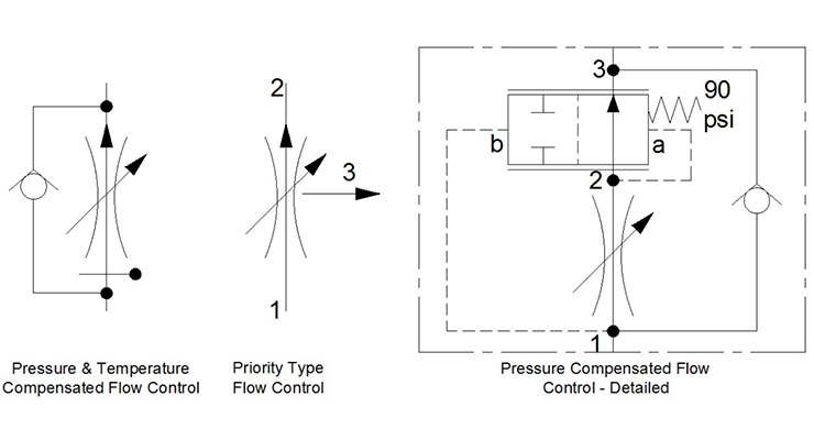
Flow Control Valves Hydraulic Symbology 4

Hydraulic Symbology 3 Pressure Valves
The Most Common Control Valve Symbols On A P Id Kimray
Directional Control Valves Symbols Hydraulic Valve

Valve Symbols Flow Control Norway As

Pneumatic Valve Symbols Directional Control Valves

Introduction To Control Valves Symbols
Pressure Relief Valve Symbol Icon Royalty Free Vector Image

File Symbol Flow Control Valve Svg Wikimedia Commons
Solenoid Valve Symbols
Control Valve With Pneumatic Actuator
Pressure Reducing Valve And Pressure Relief Valve Stuffworking Com
Control Valve Symbol High Res Stock Images Shutterstock
Book 2 Chapter 18 Pressure Relief Valves Hydraulics Pneumatics

File Control Valve Svg Wikimedia Commons

Reading Fluids Circuit Diagrams Hydraulic Pneumatic Symbols

Valve Symbols Flow Control Norway As

Flow Control Valve

Common P Id Symbols Used In Developing Instrumentation Diagrams Learning Instrument Piping And Instrumentation Diagram Electrical Symbols Control Engineering

Design Elements Valves And Fittings Valves Vector Stencils Library Interior Design Piping Plan Design Elements Piston Valve Symbol
How Does A Pressure Compensated Flow Control Valve Work Engineering360

Hydraulic Symbols Part E Www Motioninstituteonline Com Youtube


