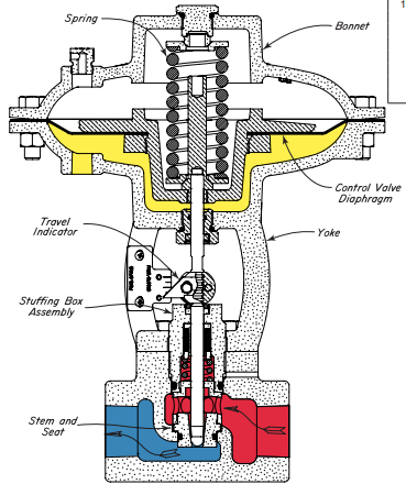
Control Valve Diagram
A gate valve is the most common type of valve used in any process plant It is a linear motion valve used to start or stop fluid flow In service, these valves are either in a fully open or fully closed position When the gate valve is fully open, the disk of a gate valve is completely removed from the flow Therefore virtually no resistance to.

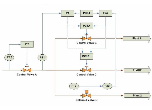
Control valve diagram. Globe Valve Diagram In the below globe valve diagram, you can see how the globe valve functions The image also shows flow direction This valve is also used as an automatic control valve, but in that case, the stem of the valve is a smooth stem rather than threaded and is opened and closed by lifting action of an actuator assembly. A ladder diagram is a topdown logical line schematic because it moves from power input at the top through sequential operations Ladder diagrams are used to draw relay control circuits, ladder diagram is different from the wiring diagram because the ladder diagram is more schematic and shows each branch of the circuit on a separate horizontal row. Medical and dental equipment use solenoid valve to control the flow, direction and pressure of the fluid Water tanks use solenoid valves to control the inflow or outflow of water, often in combination with a float switch Car washes to control the water and soap flow.
Hot water heating system zone valve installation This article describes how to wire up heating zone valves We include wiring diagrams and installation instructions for most zone valve model and multizone controllers, and we describe special wiring problems that can occur if you mix different types, brands, or models of heating zone valves on the same hydronic heating (hot water heating) system. NOMENCLATURE MODEL 2300 (3 x 2 BBL) Ref No Description Ref No Description 1 Bowl Screw GasketFuel Bowl Screw 2 3 Fuel Bowl Assembly 4 Fuel Valve Seat Lock Screw 5 Lock Screw Gasket 6 Fuel Valve Seat Adjustment Nut 7 Fuel Valve AssemblyAdjustment Nut Gasket 8 9 Float Shaft Retainer ScrewFuel ValveORing Seal 10 11 Float Lever ShaftFloat Shaft Retainer 12. The first is a Live Third Function Valve Kit, which uses a rocker switch to control the front end loader attachment This kit is designed to be run off the power beyond port of the loader valve The second type of kit is the Selector Valve Kit The selector valve kit diverts fluid using a single push button on the handle.
PLC Pneumatic Circuit Control Here we discuss about PLC Pneumatic Circuit Control with different examples PLC ladder diagram for single acting and double acting pneumatic cylinders Example 1 Double acting cylinder is used to perform machinng operation Pneumatic cylinder is advanced by pressing two push buttons simultaneously. (5A) Ignition switch control module F5 (7,5A) Sunroof control F6 (15A) Transmission control module (TCM) F7 (A) Auxiliary heater control module F8 (5A) CD changer F9 (10A) Cruise control distance range control module F10 (15A) Tow bar retract control module F11 (10A) Audio unit F12 (A/15) Sunroof control or sequential gearbox F13. Engine Valve Timing Explained Firstly, read here about how the engine valves open & closeThe engine valves are just like the human nose An automotive engine uses valves for it’s ‘breathing’ (inhale/exhale) process The engine's camshaft opens and closes the valves at a specific interval.
Water valve line thermal cutout hold switch thermostat shutoff switch water fill switch mold heater mold mounting plate 165 watts motor neutral blk blk blk blu c c c no no no nc nc nc yellow brn red grn / yel red red lt blue p3 p1 p2 p4 ice maker lt blue performance data no load & no door openings at 37°/0° control setting type a with.
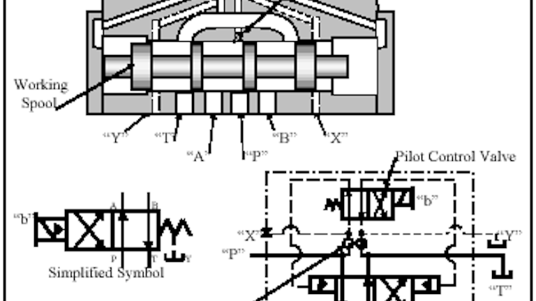
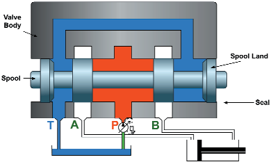
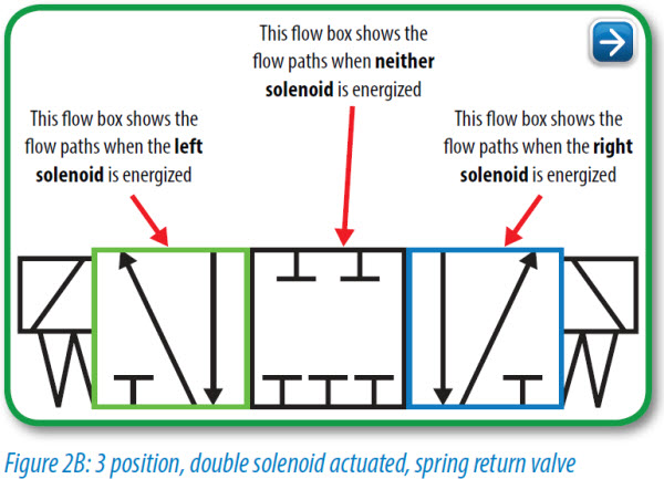
Chapter 10 Directional Control Valves Part 4 Hydraulics Pneumatics
Q Tbn And9gcqikuy7d Lutfzjwmbwfz9emf S6sgclcdsc55uyxpfrrjpkxvu Usqp Cau
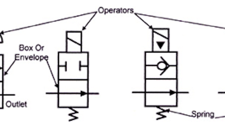
Reading Fluids Circuit Diagrams Hydraulic Pneumatic Symbols
Control Valve Diagram のギャラリー
Multi Stage Height Control Valve Including Position Sensitive Pilot Signal And Pressure Boost For Vehicle Air Springs Diagram Schematic And Image 07
Q Tbn And9gcqfdw85qdb4rohdvjzcfcgsevxuizyc7vf U7ix54s Usqp Cau

100 Series High Performance Plastic Hydraulic Control Valve 3 Way Circuit Youtube
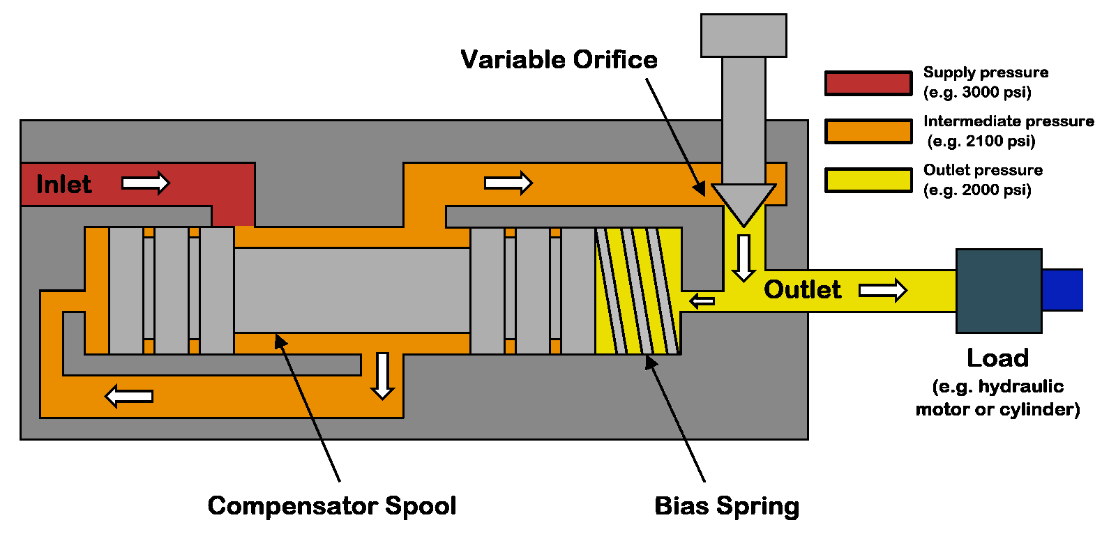
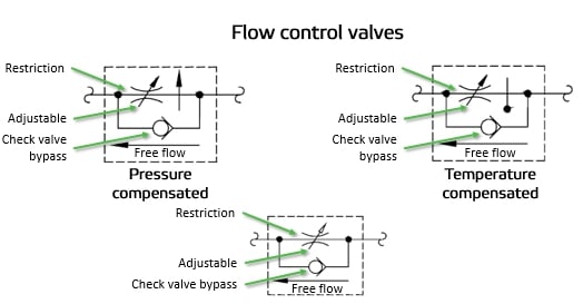
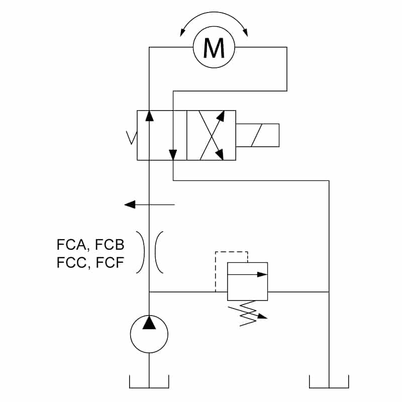
How Does A Pressure Compensated Flow Control Valve Work Engineering360
Control Valve Encyclopedia Article Citizendium
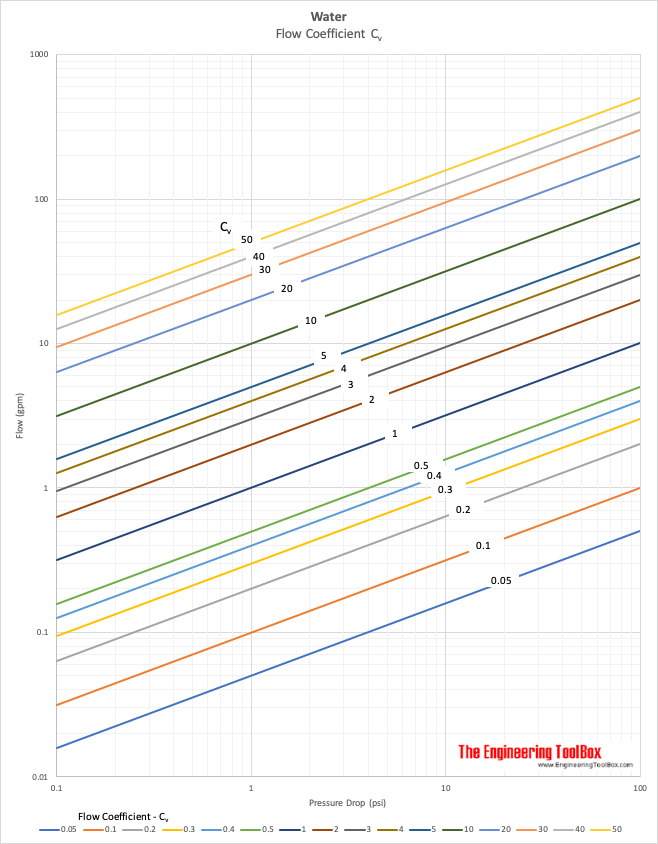
Water Control Valves Flow Coefficient I C Sub V Sub I Diagram
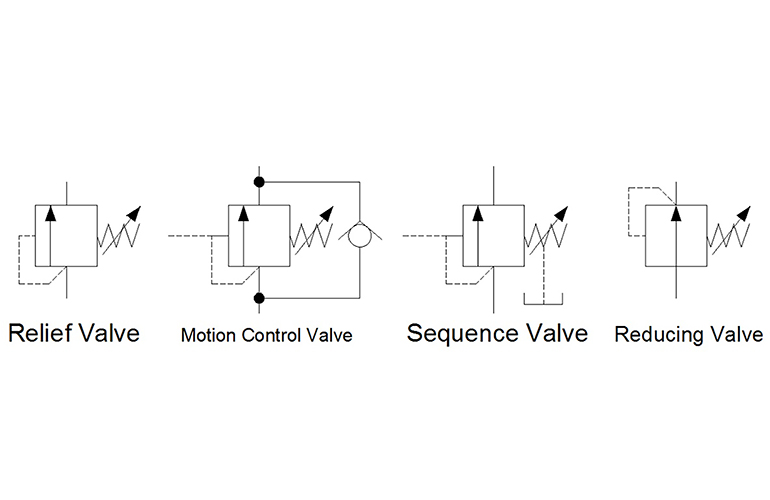
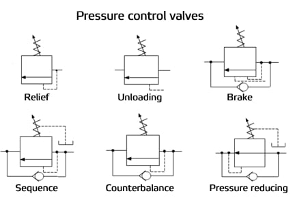
Hydraulic Symbology 3 Pressure Valves

Chapter 12 Infinitely Variable Directional Valves Hydraulics Pneumatics
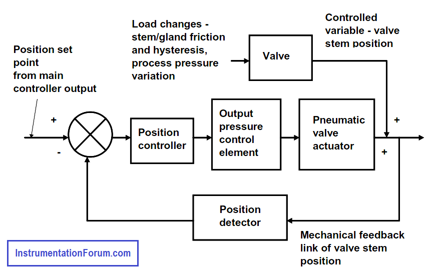
Valve Positioner Block Diagram Control Valves Instrumentation Forum

Schematic Diagram Of 3 Way Control Valve For Precision Temperature Download Scientific Diagram

Variable Flow For Hvac Systems
Valve Condition Monitoring Connected Services

Valve Positioners Basic Principles Of Control Valves And Actuators Automation Textbook

Supplement Calibration Working Control Value Isa
Globe Valve Ball Valve Gate Valve Flow Control Valve Png 681x507px Globe Valve Ball Valve Control

Fail Safe Position Selection Of Control Valve

Reading Fluids Circuit Diagrams Hydraulic Pneumatic Symbols
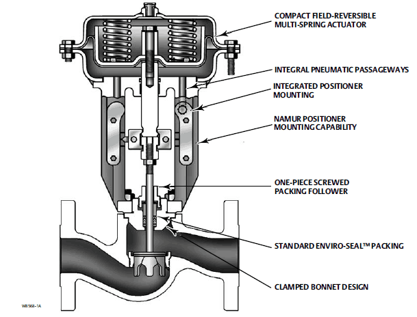
Fisher Gx Globe Control Valve Heating And Process
7 Trailer Control Valve Download Scientific Diagram

Lift Axle Control Valve Diagram Schematic And Image 02

Process Diagram Symbols Lowflow Valve Fractional Flow Control Valves Regulators

Schematic Diagram Of A Control Valve Download Scientific Diagram
Reading Fluids Circuit Diagrams Hydraulic Pneumatic Symbols
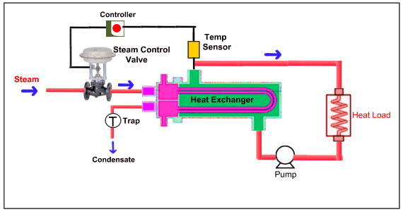
Steam Control Valve
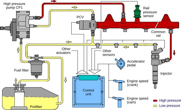
Common Rail Injection System Pressure Control

Flow Control Valves Pressure Compensated Valves Hydraulic Schematic Troubleshooting
Basic Hydraulics Directional Control Valve Blog Teknisi

3 Way Proportional Control Valve Download Scientific Diagram

Control Valve With Wide Flow Range
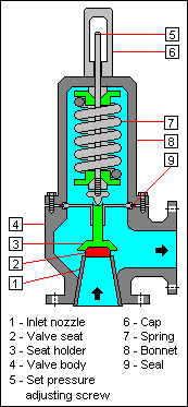
Relief Valve Wikipedia
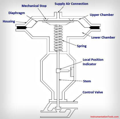
What Is A Pneumatic Actuator Instrumentationtools

Control Valve Instrumentation And Control Engineering
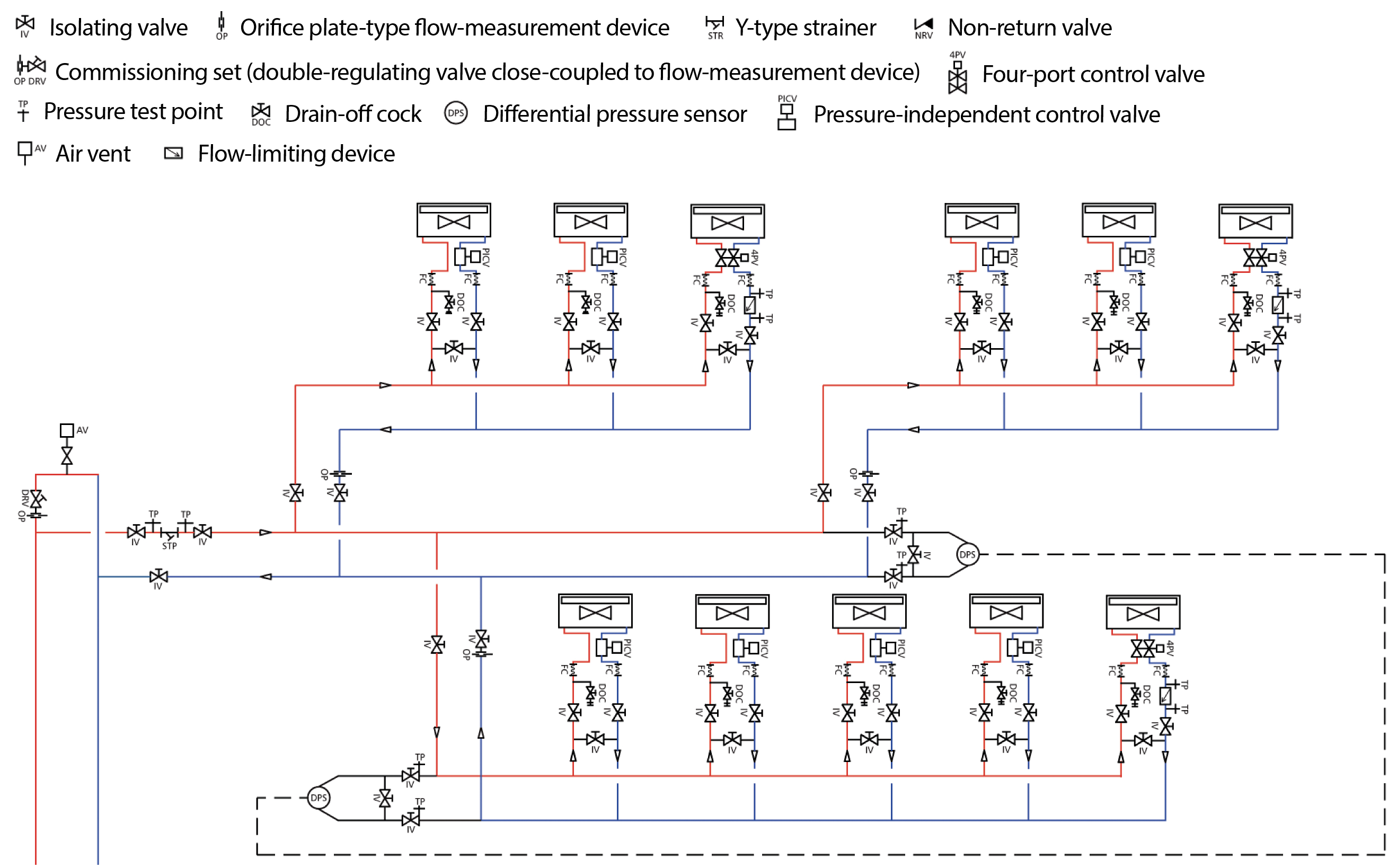
Module 140 Pressure Independent Control Valves In Variable Volume Heating And Cooling Systems Cibse Journal
Control Valves And Their Principles Of Operation

Four Port Three Position Directional Control Valve Matlab

What Does A Flow Control Valve Do
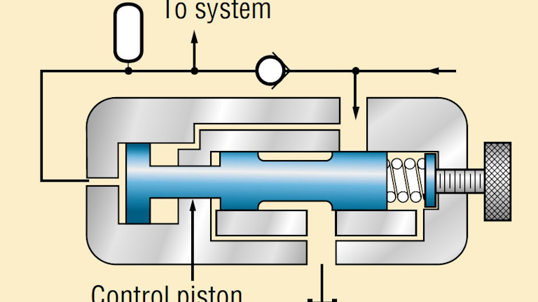
Understanding Pressure Control Valves Hydraulics Pneumatics
Book 2 Chapter 8 Directional Control Valves Hydraulics Pneumatics
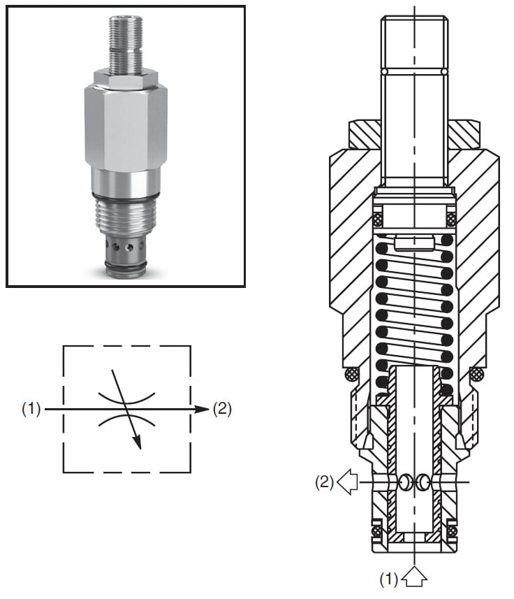
How Does A Pressure Compensated Flow Control Valve Work Engineering360

Final Control Element An Overview Sciencedirect Topics
Pneumatic Control Valve
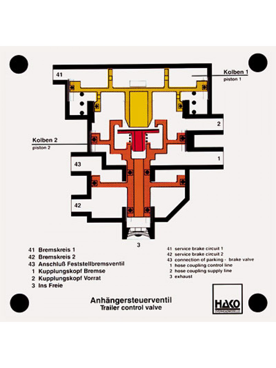
Trailer Control Valve Technolab Sa

Proportional Solenoid Valve How They Work Tameson Co Uk
Bis Valves Products Rotary Control Valve 4r25
Q Tbn And9gcq9h2gbrzqi9ptr49lihip8 Qzybektej4vytllkvgr9zv3yld9 Usqp Cau

Accessories For Control Valves
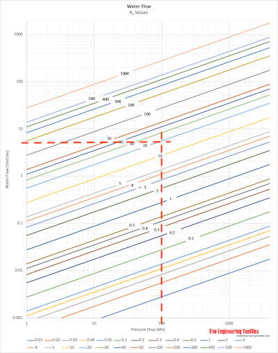
Water Control Valves Em K Sub V Sub Em Flow Coefficient Diagram
Pressure Compensated Regulator Valves Related Fluid Power
Pneumatic Circuit Symbols Explained Library Automationdirect
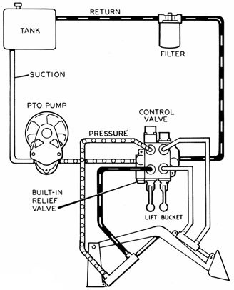
Hydraulics Systems Diagrams And Formulas Cross Mfg

Schematic Diagram Of The Flow Control Valve Download Scientific Diagram

A3 David Brown Case Tractor Brochure Poster Selectamatic Control Valve Diagram Ebay

Valve Positioners Basic Principles Of Control Valves And Actuators Automation Textbook
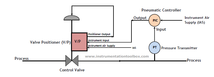
How A Pneumatic Valve Positioner Works Learning Instrumentation And Control Engineering

How A Typical Control Valve Loop Works Learning Instrumentation And Control Engineering
Bis Valves Products Directional Control Valve 3b50

Hydraulic Equipment Slowdown Nailing Internal Leakage

Flow Control Valves Regulate Speed Hydraulics Pneumatics
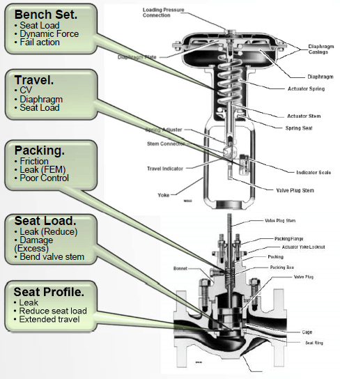
Control Valve Parts The Basics Kimray
Flow Control Valves Hydraulic Symbology 4
Control Valve Working Principle Control Valve Animation

Control Valve Parts Name Basic Knowledge Of Control Valve Parts In Hindi Youtube

Control Valve Sizing And Selection For Continuous Process Operations Processing Magazine
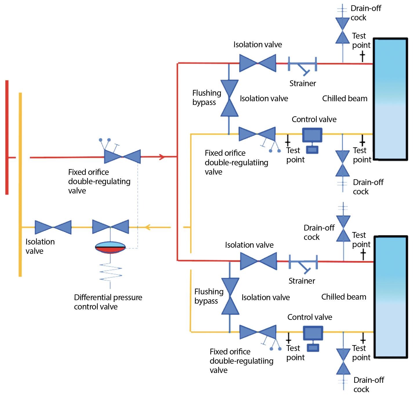
Module 140 Pressure Independent Control Valves In Variable Volume Heating And Cooling Systems Cibse Journal

Structure Of Pneumatic Control Valve Adapted From 8 Download Scientific Diagram

Flow Control Valvesmodern Industrial Hydraulics Modern Industrial Hydraulics

Pin On Instrumentation

Nice Diagram Showing The Architecture Of A Control Valve Used In Boiler Hvac Chiller Plumbing And Other Applic Control Valves Miata Mx5 Control Engineering
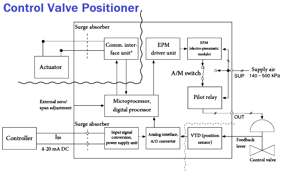
Control Valve Positioner Circuit Diagram Control Valves Instrumentation Forum
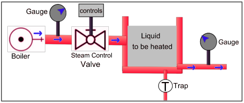
Steam Control Valve

Pin On Instrumentation

Flow Control Valves Non Pressure Compensated Valves Hydraulic Schematic Troubleshooting

Code No P0628 Suction Control Valve Open
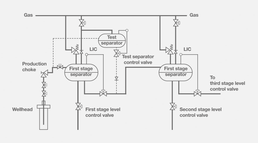
Separator Level Control Systems Kent Introl

Heater Control Valve Hcv Swartz Garage

Diagnostic Method For Detecting Control Valve Component Failure Diagram Schematic And Image 08
Control Engineering A Dual Split Range Control Strategy For Pressure And Flow Processes

Digital Control Valve Principle Control Systems Engineering Control Valves Hydraulic Systems
Valve Authority Technical Paper Control Valve Authority Fluidflow

What Is A Directional Control Valve And What Are The Types Of Dcv Instrumentation And Control Engineering

Basic Parts Of Control Valves Instrumentation And Control Engineering
Pneumatic Control Valves For Marine Pneumatic Devices

Digital Control Valve Flow Control Valves

Fortis Jaya Signs And Symptoms Of A Bad Idle Air Control Valve When Engine Problems Occur In An Automobile Causing The Vehicle To Misfire Stall Backfire Or Not Start At All
How To Install Tank Fill Control Valves Bermad

Directional Control Valves Explained
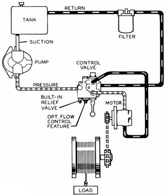
Hydraulics Systems Diagrams And Formulas Cross Mfg

Control Valve Positioner Working Principle Vrc

Smart Control Valve Positioner Control Systems Engineering Control Valves Valve
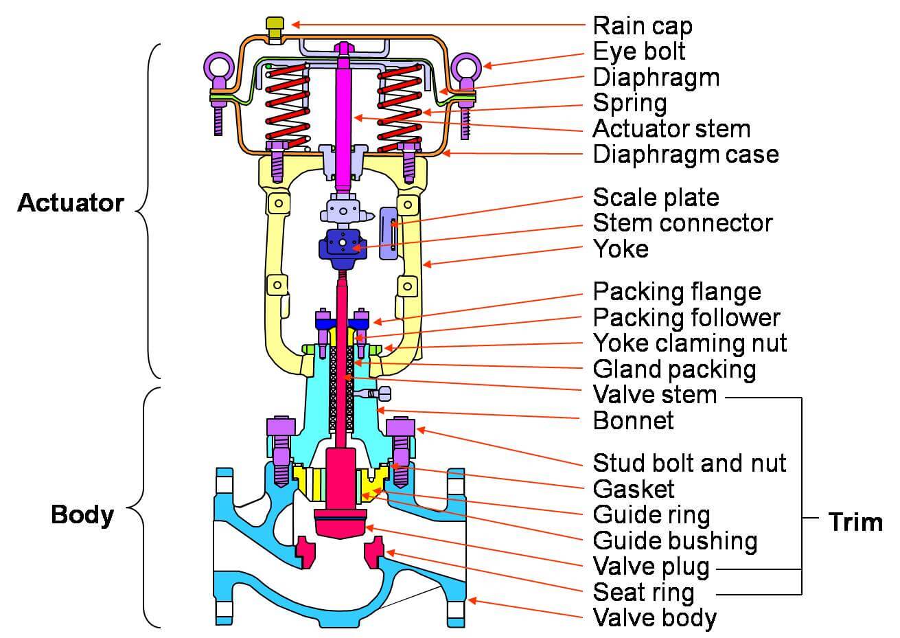
Basic Parts Of Control Valves Control Valve Functions
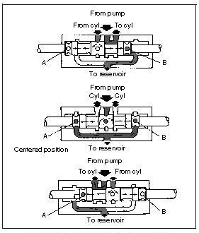
Directional Control Valves Open Center Sliding Spool Directional Control Valve Hydraulic Schematic Troubleshooting

How A Temperature Control Valve Works Learning Instrumentation And Control Engineering

How To Install A Control Valve And What Are The Types Of Actuators Used In Control Valves Instrumentation And Control Engineering

Ven 11 Lift Axle Control Valve Lift Axle System
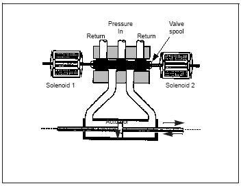
Directional Control Valves Solenoid Operated Directional Control Valves Hydraulic Schematic Troubleshooting

Hydraulic Flow Control Valves Hydraulic Valve

4 Way 3 Position Control Valve Working Construction Youtube
Hydraulic Flow Control Valves Hydraulic Valve

Valve Positioners Basic Principles Of Control Valves And Actuators Automation Textbook

Directional Control Valves Explained


